
GNSS

Base RTK

Installing Your Own RTK Base Station: What Are the Limitations?

Achieving centimetre-level GNSS accuracy relies on the use of real-time corrections. Professionals have two main options: subscribing to an RTK/NRTK network managed by a specialist provider, or installing their own fixed base station and operating independently. While having your own base station may seem appealing on paper, particularly for financial reasons, it comes with technical and operational risks that should be carefully considered before taking the plunge. How does an RTK base station work? A fixed RTK antenna (or RTK base station) is a reference station permanently installed at a point with precisely known coordinates. The base station continuously broadcasts its satellite observations and known coordinates. The GNSS receiver combines this information with its own measurements to calculate a centimetre-level position. Corrections from an RTK base station are most commonly transmitted over the internet using the NTRIP protocol (Networked Transport of RTCM via Internet Protocol). The base station continuously sends its data to a server, known as a caster, which GNSS receivers connect to in order to receive the corrections. The entire process therefore depends on the network infrastructure, which must be configured correctly: a stable, permanent internet connection, along with a properly configured router and firewall. A correction is only valid if it is recent. GNSS receivers display the “age of corrections”, meaning the time elapsed since they were transmitted. A slow or unstable connection causes these corrections to become outdated, reducing positioning accuracy and potentially resulting in the loss of the centimetre-level solution. Installing your own base station therefore also means taking responsibility for a small network infrastructure, with all the technical expertise and ongoing monitoring that entails. Reliability of positioning accuracy An RTK base station does not provide an “absolute” position. It transmits correction information based on its own reference coordinates. The receiver therefore determines its position relative to the base station. If the base station’s coordinates are incorrect, all measured positions will be shifted by the same amount and in the same direction. This is what makes the error particularly difficult to detect: the surveys remain internally consistent. Distances and shapes measured on a construction site appear correct. The offset only becomes apparent when these surveys are overlaid with other data, such as utility network plans, cadastral maps, surveys carried out by another company, or measurements taken later using an RTK network. Unlike a professional RTK network, where reference stations are continuously monitored and their coordinates regularly recalculated, a self-installed base station offers no guarantee of long-term positional stability. Maintenance An RTK base station is an active piece of equipment exposed to outdoor conditions 24 hours a day, 7 days a week. Power supply, connectivity, weather protection and component ageing are all factors that require regular maintenance. A power outage, network failure or hardware malfunction can interrupt the correction service without warning, potentially bringing operations on the construction site to a standstill. Technical dependencies Configuring an RTK base station is not a straightforward task. It requires advanced technical expertise: entering accurate known coordinates, configuring the correction transmission protocol (NTRIP), managing correction settings and ensuring compatibility with the GNSS receivers connecting to it. The base station and connected equipment are mutually dependent: changing a GNSS receiver, updating firmware or encountering a protocol incompatibility can render the entire system inoperative. Furthermore, the reference system itself evolves: the French National Institute of Geographic and Forest Information (IGN) publishes new realisations of the RGF93 reference system. The base station must be kept consistent with these developments. This requires geodetic expertise and rigorous traceability, including records of inspection dates, coordinates used and maintenance operations performed. With a professional RTK network, this responsibility lies with the network operator. Limited coverage A fixed RTK base station only covers a limited area around its installation point. The distance between the base station and the receiver is one of the factors that can affect positioning quality. Differential positioning relies, in particular, on using a reference station close enough for both receivers to observe satellite signals under similar conditions. The further the GNSS receiver moves away, the more the correction accuracy deteriorates. This is known as the baseline effect. However, this degradation is gradual and may go unnoticed by the user: there is no automatic real-time warning that positioning accuracy is deteriorating. As a result, surveys may be carried out under the assumption of centimetre-level accuracy, while the actual positioning error has reached several centimetres without the user being aware of it. A professional NRTK network, by contrast, relies on a network of reference stations that continuously calculate corrections adapted to the GNSS receiver’s position, wherever it is located within the coverage area. Syslor’s recommendation Syslor’s Proteus GNSS receiver is compatible with fixed RTK base stations: if you already have your own base station, Proteus can connect to it. However, Syslor recommends using an NRTK network operated and maintained by specialised professionals. Specialist providers such as Orphéon, Satinfo, Premium Positioning and Teria operate dense networks of reference stations that are continuously monitored and regularly recalculated. They provide extensive coverage, consistent positioning accuracy across the territory and technical support when needed. This is the approach we recommend to our customers: it makes surveys more reliable, simplifies field operations and ensures dependable positioning accuracy over time. Need advice on choosing your RTK subscription? Our team can help you select the solution best suited to your business and your projects. Contact us →

Installing Your Own RTK Base Station: What Are the Limitations? Read Post »
Trame NMEA

What Language does a GPS Receiver Speak? Understanding the NMEA 0183 Protocol.

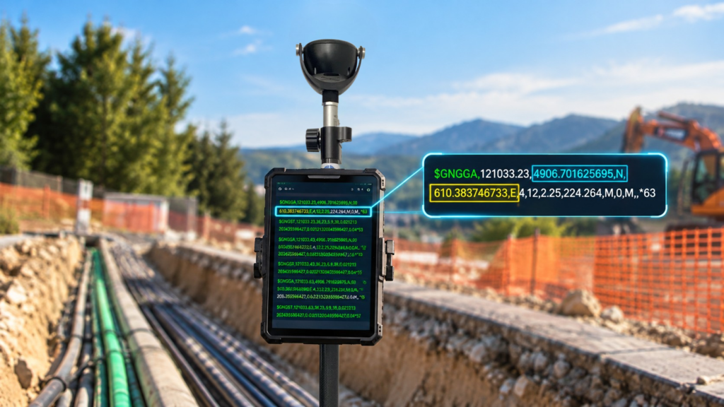
Imagine a GPS receiver connected to a field tablet. For the application to display your position, the receiver needs to “talk” to it. And it has plenty to say: time, latitude, longitude, altitude, but also speed, direction of travel (heading), positioning quality, and even the list of satellites being tracked. For all devices to understand one another, regardless of their manufacturer, they need a common language. This is the role of the NMEA 0183 standard. Originally developed for marine navigation, it is now widely used in positioning, mapping, and embedded systems. This standard organizes information into short text messages called “NMEA sentences.” Each sentence carries a specific type of information, always following the same format. This allows any compatible software to read and interpret them. NMEA 0183: Standardized Sentences In practical terms, the NMEA 0183 standard sets the rules: how data is transmitted between devices and how each message must be structured. Messages are sent as plain text in ASCII format. This means they can be read by humans, even if they may seem cryptic at first glance. Each sentence follows the same structure: It generally begins with the $ character, which indicates the start of the message; This is followed by an identifier indicating the source (for example, GP for GPS) and the type of message (for example, GGA for positioning data); Next come the data fields themselves, separated by commas; Finally, in most cases, an asterisk * is followed by a checksum, which helps verify that the message has not been corrupted during transmission. An Example of the Well-Known GGA Sentence $GPGGA,123519,4807.038,N,01131.000,E,1,08,0.9,545.4,M,46.9,M,,*47 At first glance, it looks like a sequence of letters and numbers. But by reading it field by field, we can identify: The GNSS constellation used: GPS in this case; UTC time: 12:35:19; Latitude and longitude; Position fix quality (here, 1 indicates a valid GPS position); Number of satellites used: 8; A horizontal precision indicator (HDOP): 0.9; Altitude: 545.4 meters; Geoid undulation: 46.9 metres. Checksum: 47. Watch out for a common mistake: coordinates are not expressed in decimal degrees, but in degrees and minutes. For example, 4807.038,N means “48 degrees and 7.038 minutes North,” while 01131.000,E means “11 degrees and 31 minutes East.” To convert these values into decimal degrees, simply divide the minutes by 60 and add the result to the degrees. This gives approximately 48.1173° N and 11.5167° E. The Most Common NMEA Sentences A GNSS receiver does not send just one sentence, but several, each serving a specific purpose. Think of them as sections of a newspaper: one provides position information, another reports speed, and another describes satellite status. The receiving software selects the ones it needs. Sentence Type Information Transmitted GGA Time, position, fix-related data, number of satellites, and altitude. RMC Position, speed, course over ground, time, and date. GSA Active satellites and Dilution of Precision (DOP) indicators. GSV Satellites in view, including their elevation, azimuth, and signal strength. VTG Course over ground and speed over ground. GLL Geographic position, time, and position status. ZDA UTC time, date, and time zone offset. Originally, NMEA 0183 was designed around the American GPS system, which explains why the “GP” prefix is still widely used. However, modern receivers can now track multiple constellations simultaneously, and the standard has evolved accordingly. Talker ID Meaning GP GPS solution. GL GLONASS solution. GA Galileo solution. GN Combined GNSS solution using multiple constellations. NMEA Transmits Coordinates, It Does Not Define Them It is important not to confuse NMEA 0183 with a coordinate reference system. NMEA is an interface standard: it describes how data is structured and transmitted between a GNSS receiver and software, a display, or another device. However, on its own, it does not specify the geodetic reference frame in which the position was calculated. In practice, an NMEA sentence provides latitude and longitude, but in most cases does not specify the reference frame to which they relate. This must be determined from the context: the receiver being used, its configuration, and any RTK corrections applied. NMEA transmits geographic coordinates (latitude and longitude), rather than projected coordinates in a national coordinate system such as Lambert-93 in France. Software can then interpret these sentences, display the position, and convert the coordinates into the system appropriate for the project. GPS Does Not Speak Just One Language It relies on several complementary elements: The GNSS receiver calculates a position using satellite signals; This position is generally referenced to WGS 84; It is expressed as coordinates, particularly latitude and longitude; It is often transmitted in the form of NMEA 0183 sentences; Software can then interpret these sentences, display the position, and convert the coordinates into the system appropriate for the project. In summary, NMEA 0183 is one of the communication standards that allow a GNSS receiver to exchange data with other devices. It standardizes the transmission of positioning data, but does not, on its own, define the geodetic reference frame being used. To interpret GPS coordinates correctly, it is therefore essential to understand both their transmission format and the reference system to which they relate.

What Language does a GPS Receiver Speak? Understanding the NMEA 0183 Protocol. Read Post »

GNSS positioning

GNSS – Understanding the Foundations of Satellite Positioning

GNSS positioning is used in many professional applications, including surveying, civil engineering, and utility network management. It relies on satellite constellations and complex calculation methods to determine an accurate position. Here’s a breakdown of how GNSS systems work and the common causes of accuracy degradation. GNSS: Beyond GPS The term “GPS” is often mistakenly used to refer to all satellite positioning technologies. In reality, GPS is just one of the available systems. The correct term is GNSS (Global Navigation Satellite System), which encompasses all active satellite constellations: GPS (USA) GLONASS (Russia) GALILEO (European Union) BEIDOU (China) Some regions also benefit from complementary regional systems, such as QZSS in Japan. Principles of Position Calculation A GNSS receiver calculates its position based on the measured distance between itself and several satellites. Each satellite continuously broadcasts a signal containing precise time information. By measuring the time it takes for the signal to reach the receiver, the distance can be determined. This process is known as trilateration. To compute a full position (latitude, longitude, altitude) and correct the receiver’s clock bias, at least four satellites are required. Using multiple constellations increases the number of visible satellites, thereby improving the accuracy and reliability of the positioning. Contents of GNSS Signals Each satellite transmits a signal composed of several elements. These signal structures are defined in the official GPS system specification, IS-GPS-200, published by the United States Department of Defense: Navigation data: includes orbital parameters and clock corrections. What are ephemeris data used for? Ephemeris data are orbital parameters transmitted by each GNSS satellite within its navigation messages. They describe the satellite’s trajectory over a given period and are essential for the receiver to compute the satellite’s exact position at the time the signal was transmitted. There are two main types: Broadcast ephemeris, calculated by GNSS control centers and transmitted in real time within the satellite signals. Precise ephemeris, produced by organizations such as the IGS (International GNSS Service), used in applications requiring high accuracy, especially for post-processing. An error in the ephemeris data can result in positioning errors of several meters. Their quality is therefore a critical factor in any precise GNSS computation. Precise ephemerides are particularly provided by institutions like the IGS, which supplies reference orbital and timing data used in PPP (Precise Point Positioning) solutions. Pseudo-Random Noise (PRN) code: allows identification of the satellite and calculation of the signal travel time. Carrier wave: a radio-frequency signal that carries the other data. The satellite–receiver distance can be calculated in two ways: Using the PRN code, with meter-level accuracy. Using the carrier phase, which provides centimeter-level accuracy, but requires complex processing to resolve ambiguities (such as cycle slips and the integer number of cycles). Understanding Carrier Phase Ambiguity Measuring the phase of a carrier wave allows for much higher accuracy than code-based positioning. However, it comes with a particular challenge: the receiver can measure the received phase, but does not know the exact number of whole cycles traveled between the satellite and itself. This is known as carrier phase ambiguity. To convert the measurement into an absolute distance, the ambiguity must be “resolved,” meaning the correct number of full cycles must be estimated. This step is critical in positioning techniques like RTK (Real-Time Kinematic) or PPP (Precise Point Positioning), where the accuracy directly depends on the quality of ambiguity resolution. An incorrect ambiguity “fix” results in a systematic error that can reach several centimeters or more. That’s why high-end receivers include advanced algorithms capable of detecting, modeling, and correcting these uncertainties. Ambiguity resolution is extensively documented in the literature, notably in the Springer Handbook of GNSS (Teunissen & Montenbruck, 2017), a key reference on the topic. Main Sources of GNSS Errors Several factors affect positioning accuracy. Errors may arise from: From the satellites: Clock errors: although satellites are equipped with atomic clocks, even tiny drifts can cause positioning errors of several meters. Orbital errors: discrepancies exist between the satellite’s theoretical position and its actual position. From the atmosphere: Ionospheric delay: caused by charged particles in the upper atmosphere; it varies with solar activity. Tropospheric delay: caused by humidity and pressure in the lower layers of the atmosphere. From the receiver: Internal clock drift Local environment errors: such as multipath effects, obstructions, and interference. Cycle slips: an intermittent but critical source of error A cycle slip is a sudden disruption in the tracking of a carrier phase signal by a GNSS receiver. This typically occurs when a temporary obstacle (such as a vehicle, building, or vegetation) blocks or disturbs the signal, even momentarily. When the signal is reacquired, the receiver resumes phase tracking, but the previous ambiguity is no longer valid—it must be re-estimated. If this detection is poorly handled, it can result in an invisible but long-lasting error. High-performance receivers, such as Proteus, are equipped with automatic cycle slip detection mechanisms and can restart ambiguity resolution algorithms accordingly. Effective handling of cycle slips is critical in complex environments such as urban areas, forests, or cluttered construction sites. Signal processing accuracy: depends on the quality of the hardware and the algorithms used.   Type of error Origin Order of magnitude Satellite clock drift Space segment Up to 3 meters Orbital error Space segment ±2.5 meters Ionospheric delay Atmosphere (50–1000 km) 5 to 50 meters Tropospheric delay Atmosphere (0–12 km) 2 to 10 meters Multipath Receiver / Environment Variable (meters) Internal measurement noise Receiver Centimeter to decimeter level Improving Accuracy: GNSS Corrections To achieve centimeter-level accuracy, GNSS positioning must be corrected. Several techniques exist depending on the use case and operating conditions: RTK (Real-Time Kinematic) and NRTK (Network RTK): use one or more fixed reference stations to provide real-time correction data. The differential correction data are usually transmitted in the RTCM 10403.3 format, a widely adopted standard in professional GNSS systems. Base/Rover: involves a mobile base station that sends corrections to a rover in real time. This method requires solid surveying knowledge for proper setup. PPP (Precise Point Positioning): uses mathematical models to correct various error

GNSS – Understanding the Foundations of Satellite Positioning Read Post »

Syslor: A Labeled Innovation for Smart Utility Network Management

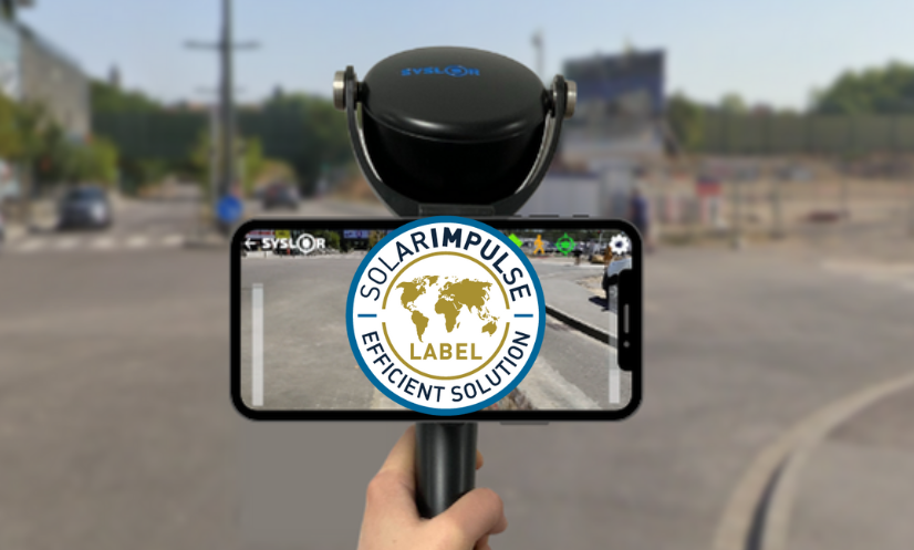
The Proteus GNSS receiver labeled “Solar Impulse Efficient Solution” In a world where environmental challenges are becoming increasingly urgent, concrete and cost-effective solutions are essential. In this context, Syslor was awarded the “Solar Impulse Efficient Solution” label in 2021 for its GNSS receiver named Proteus, marking a key milestone in its commitment to sustainable innovation. In 2024, this recognition was renewed, highlighting the continued relevance of the Proteus solution in addressing the challenges of ecological transition. What is the “Solar Impulse Efficient Solution” label? Created by the Solar Impulse Foundation, founded by Swiss explorer Bertrand Piccard, this label recognizes solutions that combine environmental performance with economic viability. Its goal is to promote 1,000 clean technologies capable of accelerating the ecological transition without compromising profitability. To earn this label, each solution is assessed by independent experts based on three criteria: feasibility, environmental impact, and profitability. Proteus: A Labeled Innovation for Smart Utility Network Management The Proteus technology, developed by Syslor, has successfully met these strict requirements.It is a real-time geo-referencing solution for underground utility networks, which enables: Reduced costs related to interventions and network damage Lower environmental impact of construction works Improved accuracy and traceability of operations Smoother communication between construction and public works stakeholders Thanks to this innovation, local authorities, public works companies, and utility managers have a practical tool to reduce their carbon footprint while optimizing their operations. View the official Proteus listing on Solar Impulse A Recognition That Reinforces Syslor’s Mission Being labeled by the Solar Impulse Foundation means joining an international community of providers of sustainable and efficient solutions. For Syslor, it represents a strengthened commitment to meaningful and responsible innovation. The renewal of the label in 2024 confirms the robustness and added value of Proteus, and reinforces our ambition to provide stakeholders with practical tools to address the challenges of the energy transition — with a focus on local impact, reliability, and performance. In conclusion By joining this initiative, Syslor is committed to putting technology at the service of a more sustainable future — without compromising on efficiency.

Syslor: A Labeled Innovation for Smart Utility Network Management Read Post »

Récepteur GNSS Reach Rx Reach RS3 Emlid

SYSLOR Solutions Now Compatible with New GNSS Receivers: Focus on Emlid’s Reach RX / RS3

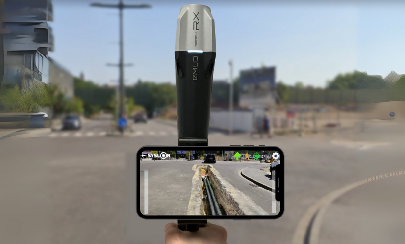
The Reach RX/RS3, like many other GNSS receivers, uses the NMEA format, a universal standard for transmitting positioning data. By leveraging this protocol, we ensure that our applications are compatible with a wide range of GNSS receivers available on the market. This standardized approach offers several advantages: Simplified integration with various GNSS equipment Proven reliability in data transmission Greater flexibility in choosing your hardware With this in mind, we have expanded the compatibility of our applications to include Emlid Reach RX and Reach RS3 GNSS receivers, carefully integrating their technical features (offsets, inertial measurement unit, etc.). A More Open SYSLOR Ecosystem, Designed for Real-World Field Operations Practically speaking, you can now connect your Reach RX/RS3 directly to: EasyField, for intuitive staking and topographic surveying, EasyView, to visualize your networks, plans, and 3D models in augmented reality, EasyScan, to capture your trenches from a video and generate a certified as-built plan (Class A certification). All on Android, with no complex setup: direct Bluetooth connection, automatic GNSS stream recognition, and continuous RTK service support. Choosing SYSLOR Means Choosing a Field-Centric Solution Intuitive interface, even without surveying experience Web portal for project data tracking and management Real-time synchronization between the field and the office A responsive hotline to support you daily Regular technical updates and new features Our promise: to support you from the field to the office with a coherent, scalable system tailored to your real-world needs. Already Working with a Reach RX? Activate Compatibility Today Already using a REACH RX/RS3 on your projects and want to benefit from SYSLOR’s features? Contact our team at contact@syslor.net to activate the connection and start your projects without delay.

SYSLOR Solutions Now Compatible with New GNSS Receivers: Focus on Emlid’s Reach RX / RS3 Read Post »

Scroll to Top