EasyScan

How Merging Orthophotos and Point Clouds Enhances Project Accuracy

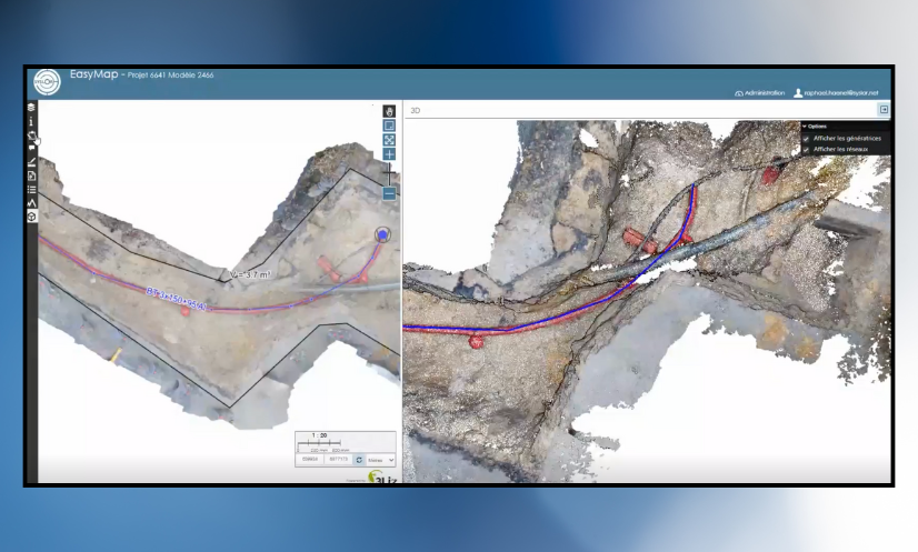
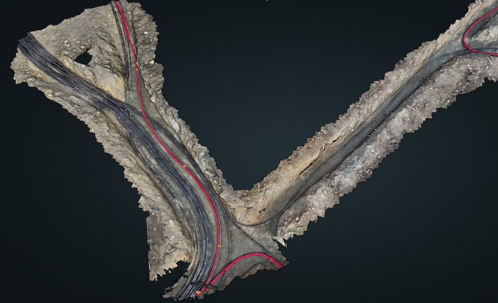
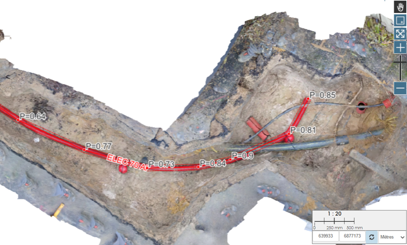
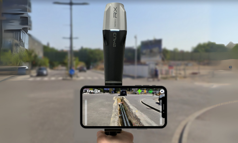
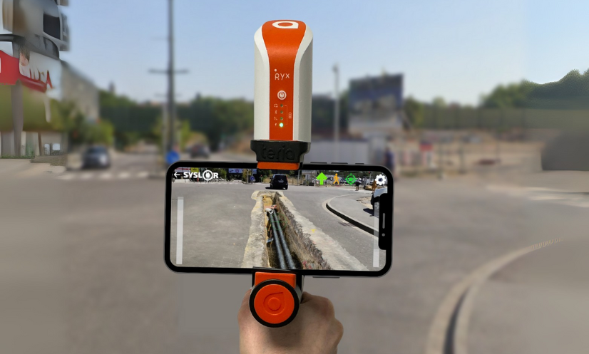
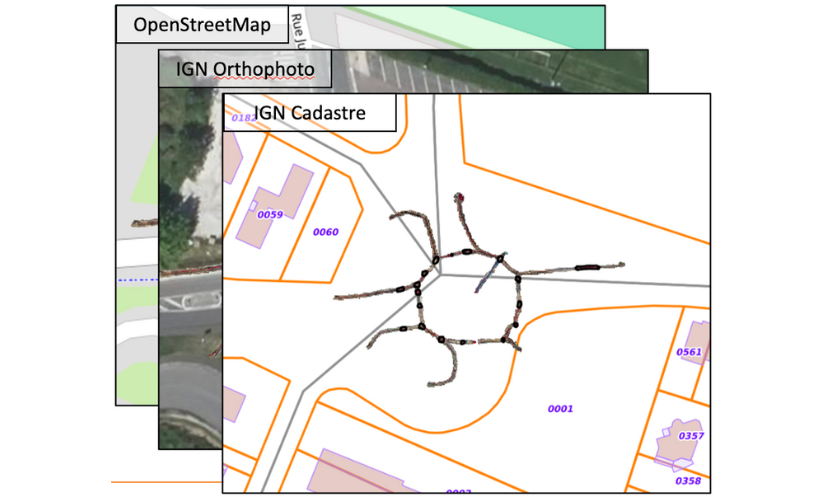
On construction sites, each photogrammetric survey generates its own dataset — an orthophoto, a point cloud, sometimes dozens of separate files to manage. Over time, these fragmented deliverables become difficult to work with. Misaligned joins, overlapping zones, or missing areas can compromise the overall topographic consistency of the project. For surveyors, engineering offices, and project managers, the issue is often the same: getting a comprehensive and accurate view of the site requires time-consuming manual work, which increases the risk of errors. This is exactly the challenge addressed by the merging of orthophotos and point clouds.By bringing all survey data together into a single, unified, georeferenced model, this process delivers a continuous, coherent, and readily exploitable view of the project. Beyond improving readability, accuracy, and efficiency across the entire production chain, it also saves a significant amount of time for survey teams when preparing their deliverables. To better understand its advantages, let’s start by defining what the merging of orthophotos and point clouds actually is. What Does Merging Involve? Merging consists of combining several separate orthophotos or point clouds into a single, unified, and consistent view, while preserving the original centimetric accuracy and georeferencing.Each area captured during the photogrammetric survey is repositioned within the same coordinate system to create a continuous mosaic of the project. The merging process relies on rigorous management of metadata and spatial coordinates. This ensures that all datasets align perfectly — without offset, elevation gaps, or quality loss. The result is a unified model that faithfully represents the entire site, enabling consistent and accurate measurements across the whole area. With this merging process in place, it becomes possible to visualize, measure, and vectorize an entire project from a single unified dataset, regardless of the project’s size or complexity. Now that the concept of merging is clear, let’s look at how it concretely improves the production and use of photogrammetric deliverables. Why Merge Your Photogrammetric Deliverables? Merging is not just a simple file combination — it’s a key step that allows teams to fully leverage the richness of photogrammetric data while ensuring the consistency of all deliverables.Here are the main advantages it brings, both in the field and in the office. Gain a Global View of the Project and In-Situ Context Merging provides a comprehensive view of the construction site, restoring the entire area within a single, continuous representation.It makes it possible to place each work zone within its broader environment — a valuable advantage for large-scale sites or linear projects such as roads, utilities, or railway corridors. This unified view helps teams understand how different areas interact, for example between the construction footprint, the surrounding environment, and existing underground or above-ground networks. Improve Vectorization Accuracy and Spatial Consistency By merging several orthophotos or point clouds within the same reference system, merging eliminates alignment errors between deliverables.It ensures a homogeneous topographic continuity, which is essential for: the precise vectorization of utility networks, the production of reliable as-built plans, and volume or surface calculations. Each measurement is therefore based on a coherent, georeferenced dataset, with no risk of misalignment between areas. Simplify the Use of Your Deliverables Through Centralized Data With merging, there’s no need to juggle multiple files anymore.Orthophotos and point clouds are grouped into a single unified view, speeding up processing and reducing the risk of errors during plan production or verification. This approach also simplifies importing deliverables into standard GIS or CAD software (DGN, DXF, CSV): a single, complete, georeferenced file, immediately ready for use by all project stakeholders. Enhance Collaborative Work By providing a single, consistent source of truth, merging makes collaborative work much easier.Everyone works from the same reference dataset, improving both validation and quality control of deliverables throughout the entire project lifecycle. Looking Ahead: Tracking Project Progress Over Time In the long term, merging opens the door to new possibilities: tracking the evolution of a construction site over time, overlaying successive surveys (before and after works), and building a true digital twin of the project. This approach will make it possible to accurately analyze site transformations — from earthworks to network installation — and to ensure complete traceability of all operations. How Syslor Facilitates the Merging of Orthophotos and Point Clouds The merging of orthophotos and point clouds truly reveals its value when it’s part of a seamless workflow — from data capture in the field to data processing and analysis. This is exactly what Syslor offers through two complementary solutions: EasyScan for photogrammetric surveying, and EasyMap for the visualization and processing of deliverables. EasyScan – Accurate and Standardized Photogrammetric Capture Everything starts in the field with EasyScan, the solution designed to perform georeferenced photogrammetric surveys. Each survey performed with the EasyScan application ensures centimetric accuracy and structured, standardized data.As a result, right from the survey phase: orthophotos and point clouds are perfectly aligned within the same reference system; deliverables are immediately available in EasyMap for further processing and analysis. EasyMap – Merging and Centralized Management of Deliverables Once the surveys are completed, EasyMap (formerly Sysmap) takes over. The tool, available directly through the Syslor web portal, assembles orthophotos and point clouds from different photogrammetric surveys to generate a unified overview of the entire project. The user then gains access to a comprehensive environment to: visualize the construction site as a whole, vectorize networks on a consistent base, perform measurements and volume calculations without discontinuities, and export reliable as-built plans with full confidence. This automation ensures a smooth, continuous production workflow, from field survey to final deliverable delivery. Ready-to-Use and Interoperable Deliverables Thanks to the complementarity between EasyScan and EasyMap, all data is aligned, merged, and immediately usable across any working environment — CAD, GIS, or collaborative platforms.The result: greater accuracy, less post-processing, and improved traceability throughout the entire project lifecycle. Want to learn more? Request a demo. A Unified Vision for More Accurate and Actionable Deliverables The merging of orthophotos and point clouds is not just a technical step — it’s a key requirement for ensuring the reliability and readability of

How Merging Orthophotos and Point Clouds Enhances Project Accuracy Read Post »

EasyMap News - October 2025

Customized Attribute Libraries, 3D Editing, and Model Concatenation: What’s New at Syslor? 

Syslor is enhancing its EasyMap platform with three new features that make daily operations even smoother for field and design teams. EasyMap is the drawing and tracing tool accessible directly from the Syslor portal, used by EasyScan users to edit orthophotos and point clouds generated from photogrammetric surveys. It enables users to transform survey data into usable plans, control altimetry, and monitor project progress.  The new features focus on three key aspects:  Customizable vectorization,  The move from 2.5D to full 3D,  Model concatenation for an overall project view.  All these improvements share a common goal: simplify deliverable production, increase accuracy, and ensure better continuity between all project stakeholders.  Customize Vectorization to Match Your Standards Attribute Libraries Tailored to Your Needs Every company applies its own mapping standards. EasyMap now includes customizable attribute libraries, grouping the necessary object families (electricity, water, heating, telecom, wastewater, etc.) in line with your internal practices. Ready-to-Use, Standards-Compliant Exports Generated plans automatically comply with your nomenclatures and export formats (DXF, DGN, etc.). No more manual adjustments — exports from EasyMap are structured, standardized, and complete, saving time and reducing the risk of error.  Control and Edit in 3D While Keeping the Simplicity of 2.5D The Limits of 2.5D 2.5D remains widely used because it’s lightweight and easy to handle. However, it reaches its limits when verifying altimetry or working with overlapping networks. On the other hand, navigating within a 3D view allows for continuous control, but it is less intuitive and straightforward due to the complexity of three dimensions. Dual View for Greater Precision EasyMap now offers a dual view: a classic 2.5D view on the orthophoto to maintain the simplicity of tracing, a 3D view of the point cloud to verify altimetric consistency and interact directly with objects. Thanks to this combination, it is now possible to: draw networks on the orthophoto while simultaneously checking the accuracy and diameters within the point cloud, edit in 3D, allowing users to trace networks or modify a point directly in the point cloud and instantly visualize the impact on the orthophoto. This interaction between the point cloud and the orthophoto greatly enhances the accuracy of as-built documentation. Concatenate Models for a Complete Project Overview Global Project Management and Tracking Model concatenation automatically groups multiple photogrammetric surveys into coherent zones. This provides not only a macro view of the project but also continuous monitoring of its progress. This global approach facilitates project management, team coordination, and the progressive updating of data throughout the project. Global statistics (lengths, network types, progress rates) offer a clear and centralized overview. The choice of the background map allows for better contextualization of the project. Continuity and Unified Export Overlapping areas are automatically flagged as attention points. A dedicated process ensures topological continuity between models, reducing connection errors and ensuring smooth, uninterrupted tracing. The entire project can then be exported as a single, consistent file in all standard industry formats. Result: a single, fast, and consistent export, directly usable in standard industry formats (CSV, DXF, DGN, etc.), with no manual post-processing required. A Step Toward Greater Automation These new features already simplify users’ daily workflows by reducing manual corrections and improving coordination. They also mark the next step in Syslor’s broader roadmap: 3D tracing, AI-assisted drawing, and georeferenced annotations will soon further enrich the EasyMap experience.

Customized Attribute Libraries, 3D Editing, and Model Concatenation: What’s New at Syslor?  Read Post »

Photogrammetry: principles, method and use cases

What is photogrammetry? Photogrammetry is a technique for generating 3D restitution from 2D images. In practice, it makes it possible to model terrain with high precision, without contact, by exploiting the principle of parallax between several photos taken from different angles. Historically, it was first used in geomatics. Today, this method finds concrete applications in the fields of topography, public works, and network management. For its part, Syslor leverages photogrammetry using video captures made directly in the field by users via the EasyScan application, from a smartphone or tablet. These videos are then processed to produce georeferenced orthophotos and 3D models that can be used in our visualization and vectorization portal. Finally, this article outlines the basic principles of photogrammetry, its key steps, the deliverables generated, as well as its main field applications. Types of photogrammetry (analytical, digital) Depending on the evolution of techniques and available tools, photogrammetry can be implemented in different ways. Two main approaches are generally distinguished, which differ in their level of automation and the calculation methods used: Analytical photogrammetry: based on manual or semi-automated geometric calculations. Digital photogrammetry: fully computer-based, it relies on matching algorithms and image processing. How does photogrammetry work? Beyond its theoretical principle, photogrammetry relies on a well-structured processing workflow that transforms simple images into usable geometric data. From the automatic identification of common points to the generation of orthophotos and 3D models, each step contributes to ensuring the precision and consistency of the final result. Here are the main stages of this process: Matching of homologous points The software automatically identifies identical points (tie points) present in multiple images, usually by using correlation methods or feature detection. In practice, this avoids the need for the operator to manually capture every detail and ensures a solid foundation for reconstructing the site in 3D. Parallax and triangulation in photogrammetry The difference in angle between images makes it possible to calculate the 3D position of each point through triangulation. This mathematical process results in an accurate 3D model of the trench or surveyed surface, which can then be directly used to measure distances, depths, or verify the location of utilities. Image overlap conditions (forward and side overlap) To obtain a coherent and complete model, it is necessary to ensure: A forward overlap of at least 70% between two consecutive images, A side overlap of at least 30% between two flight lines. In practice, this means that operators must capture photos or videos in a regular and structured way, ensuring that the software can accurately reconstruct every part of the site without missing areas. Steps of the photogrammetry processing workflow Image alignment: recognition of common points and relative orientation. Generation of the 3D point cloud: dense, structured, and accurate. Production of the DTM/DSM: extraction of topographic surfaces. Orthophotography: planar, distortion-free, and georeferenced projection. Data export: standard formats for GIS/CAD integration. Photogrammetry deliverables: what results can you obtain? Orthophoto A georeferenced image in planar projection, free from distortion, that can be used as a base map for layouts or surveys. It is the equivalent of a “photo plan” of the construction site, serving as a reliable background for mapping utilities and producing a compliant as-built record. Digital Surface Model (DSM) and Digital Terrain Model (DTM) DSM (Digital Surface Model): includes visible surface objects (vegetation, buildings). DTM (Digital Terrain Model): represents only the bare ground surface, without obstacles. Photogrammetric 3D point cloud Resulting from triangulation, it enables the detailed reconstruction of terrain, structures, and volumes. For the user, this is equivalent to having a digital copy of the site, which can be revisited at any time to perform measurements or provide evidence of the work carried out. Export to GIS / CAD formats The data can be exported in standard formats (.tif, .las, .dxf, .shp, .gml, etc.) for integration into CAD or GIS software. Photogrammetry in the field: what is it used for? Photogrammetry is particularly useful for: Large-scale surface surveys, even in areas that are difficult to access. Construction site visualization, including topography, access, obstacles, and interfaces. Utility marking and as-built plans, where orthophotos allow the visual integration of surveyed networks. Vectorization within professional platforms, where the orthophoto serves as a reliable base for accurately mapping utilities, as in the Syslor interface. Applying photogrammetry to underground utility mapping and as-built documentation In the context of underground utility as-built surveys, photogrammetry provides an effective response to both regulatory and operational requirements. In practice, from videos or images taken during trench openings, it is possible to generate georeferenced orthophotos and 3D point clouds that accurately document the condition of the terrain and the position of installed utilities. Subsequently, the data are integrated into GIS, CAD, or CAE environments using standard formats (.tif, .las, .dxf, .shp, .gml), thus ensuring their usability by all project stakeholders. When combined with centimetric GNSS positioning (RTK/NRTK) or ground control points (GCPs), this method guarantees absolute accuracy in line with as-built requirements. The benefits of photogrammetry in this context are multiple: Damage evidence: the orthophoto serves as an objective record in the event of damage to utilities or incidents related to construction work. Traceability and history: each intervention is documented and archived, providing a reliable basis for monitoring utilities. Damage prevention: accurate knowledge of the subsurface and existing utilities reduces risks during future operations. Asset management: the generated data enrich cartographic databases and facilitate the long-term management of infrastructures. Ultimately, by combining photogrammetry with centimetric GNSS measurements, it becomes possible to produce an as-built survey that is exhaustive, accurate, and reliable as a reference in the event of inspections or disputes. This approach effectively addresses safety, regulatory compliance, and cost-control challenges related to damages. With EasyScan, operators simply record the trench using a smartphone. The videos are automatically transformed into georeferenced orthophotos and accurate 3D models, which are then integrated into the Syslor portal for vectorization. Combined with the centimetric GNSS receiver Proteus, the solution ensures a reliable as-built survey that is immediately usable by all project stakeholders. In summary Photogrammetry is a

Photogrammetry: principles, method and use cases Read Post »

How to process and exploit point clouds effectively?

Photogrammetry has become an essential technique for documenting and analyzing construction sites, particularly in the context of as-built surveys of underground networks.It enables the production of georeferenced deliverables in various forms, such as point clouds, orthophotos, digital terrain models (DTMs), or even 3D meshes. Photogrammetric deliverables can be difficult to leverage due to the complexity of the data and the analyses required.Fortunately, some software tools—such as EASYMAP®—accessible through our web portal, greatly simplify this process, making these deliverables far more accessible to non-expert users. Let’s explore the practical applications of data collected using as-built tools like EasyScan®. Solutions for leveraging data collected through as-built surveys Vector mapping of utility networks Combining orthophotography with a digital terrain model (DTM) enables vertical projection, making it easy, fast, and accurate to vectorize the upper generatrices in 3D. This vectorization can be exported in various formats, allowing it to be used and integrated into Geographic Information Systems (GIS) or Computer-Aided Design (CAD) software, ensuring smooth interoperability between all project stakeholders. Example of upper generatrix tracing of an electrical network using Sysmap Handling longitudinal and cross-sectional profiles This vectorization comes with the ability to generate longitudinal and cross-sectional profiles, enabling continuous control of the tracing process. This ensures tracing reliability that meets the accuracy requirements of Class A. Profiles based on an electrical duct Longitudinal profile Cross-sectional profile Profiles produced with Sysmap Area measurement and cut/fill volume computation The drawing interface allows users to measure the surface areas of intervention zones, making it possible to directly assess excavated areas and optimize land use.This surface also serves as the basis for precise volumetric measurements.The Sysmap solution helps optimize earthwork costs by providing accurate resource estimates and ensuring project compliance. Area and volume computations using Sysmap Depth measurement of utility networks During network as-built surveys, photogrammetric deliverables make it possible to determine the depth of vectorized vertices from a reference surface — a crucial element for: Ensuring compliance with safety and utility location standards; Improving the quality of as-built plans by providing accurate data on pipeline burial depths. Detection of unusual depth values using Sysmap Photogrammetric deliverables go far beyond simple visualization: they enable the extraction of numerous precise measurements—vectorization, surface area, volume, depth—making them true decision-support tools for site managers and agency directors.They enhance as-built survey accuracy, optimize costs, and contribute to better management of underground infrastructure. With Sysmap—our tracing module designed to leverage photogrammetric deliverables—network tracing is performed with precision.This process ensures reliable, usable data that is essential for future projects: building asset records, reducing damage to infrastructure, saving time, and optimizing upcoming interventions. By combining high-quality surveys with dedicated tools like Sysmap, photogrammetric deliverables become true management assets—enabling more efficient and better-anticipated construction projects.

How to process and exploit point clouds effectively? Read Post »

Récepteur GNSS Reach Rx Reach RS3 Emlid

SYSLOR Solutions Now Compatible with New GNSS Receivers: Focus on Emlid’s Reach RX / RS3

The Reach RX/RS3, like many other GNSS receivers, uses the NMEA format, a universal standard for transmitting positioning data. By leveraging this protocol, we ensure that our applications are compatible with a wide range of GNSS receivers available on the market. This standardized approach offers several advantages: Simplified integration with various GNSS equipment Proven reliability in data transmission Greater flexibility in choosing your hardware With this in mind, we have expanded the compatibility of our applications to include Emlid Reach RX and Reach RS3 GNSS receivers, carefully integrating their technical features (offsets, inertial measurement unit, etc.). A More Open SYSLOR Ecosystem, Designed for Real-World Field Operations Practically speaking, you can now connect your Reach RX/RS3 directly to: EasyField, for intuitive staking and topographic surveying, EasyView, to visualize your networks, plans, and 3D models in augmented reality, EasyScan, to capture your trenches from a video and generate a certified as-built plan (Class A certification). All on Android, with no complex setup: direct Bluetooth connection, automatic GNSS stream recognition, and continuous RTK service support. Choosing SYSLOR Means Choosing a Field-Centric Solution Intuitive interface, even without surveying experience Web portal for project data tracking and management Real-time synchronization between the field and the office A responsive hotline to support you daily Regular technical updates and new features Our promise: to support you from the field to the office with a coherent, scalable system tailored to your real-world needs. Already Working with a Reach RX? Activate Compatibility Today Already using a REACH RX/RS3 on your projects and want to benefit from SYSLOR’s features? Contact our team at contact@syslor.net to activate the connection and start your projects without delay.

SYSLOR Solutions Now Compatible with New GNSS Receivers: Focus on Emlid’s Reach RX / RS3 Read Post »

Récepteur GNSS Pyx Teria

SYSLOR Apps and Teria’s PYX GNSS receiver: Precision and Simplicity for Safer, Faster Worksites

To provide field operators with powerful software solutions and support them more effectively in their daily challenges, SYSLOR has extended the compatibility of its solutions to a new flagship GNSS receiver. A Hardware-Software Partnership Serving On-Site Precision By partnering with Teria, SYSLOR reinforces its ability to deliver a simple, reliable, and autonomous working environment tailored to the needs of modern utility and infrastructure worksites. Beyond the technical aspects, this compatibility reflects a shared vision of on-site performance, driven by two companies with the same ambition: to innovate with solutions designed and manufactured in France. A Connected and User-Friendly Environment SYSLOR solutions are designed to be accessible to all field operators, without requiring technical expertise. They are compatible with all Android smartphones and tablets, and are supported by a collaborative web portal aimed at surveyors, CAD designers, and other stakeholders — enabling centralized data processing, project tracking, and streamlined deliverable management. Seamless Compatibility Within the SYSLOR Ecosystem Thanks to GNSS protocol integration, SYSLOR solutions can be connected to the PYX GNSS receiver immediately via the mobile applications installed on phones or tablets, ensuring a smooth, reliable, and ready-to-use field experience. Integrating PYX into SYSLOR’s Technical Environment To ensure full compatibility with the PYX, our engineers integrated the receiver into the SYSLOR portal and synchronized the antenna, handle, and camera constants with the three SYSLOR applications: EasyField for precise staking and data collection of points, lines, and surfaces EasyView to visualize underground networks in augmented reality directly in the field EasyScan to capture open trenches (photogrammetry) and generate a compliant as-built plan with class A accuracy The user’s usual RTK correction service can still be used, regardless of the worksite conditions. This development strengthens SYSLOR’s commitment to delivering an interoperable, intuitive, and ready-to-deploy work environment that meets the growing demands of underground infrastructure projects and enhances the overall user experience. Do you already use a Pyx receiver and want to connect it to SYSLOR applications? Write to us at contact@syslor.net to activate the connection and get started quickly.

SYSLOR Apps and Teria’s PYX GNSS receiver: Precision and Simplicity for Safer, Faster Worksites Read Post »

Scroll to Top