GNSS positioning is used in many professional applications, including surveying, civil engineering, and utility network management. It relies on satellite constellations and complex calculation methods to determine an accurate position. Here’s a breakdown of how GNSS systems work and the common causes of accuracy degradation.
GNSS: Beyond GPS
The term “GPS” is often mistakenly used to refer to all satellite positioning technologies. In reality, GPS is just one of the available systems. The correct term is GNSS (Global Navigation Satellite System), which encompasses all active satellite constellations:
GPS (USA)
GLONASS (Russia)
GALILEO (European Union)
BEIDOU (China)
Some regions also benefit from complementary regional systems, such as QZSS in Japan.
Principles of Position Calculation
A GNSS receiver calculates its position based on the measured distance between itself and several satellites. Each satellite continuously broadcasts a signal containing precise time information. By measuring the time it takes for the signal to reach the receiver, the distance can be determined. This process is known as trilateration.
To compute a full position (latitude, longitude, altitude) and correct the receiver’s clock bias, at least four satellites are required. Using multiple constellations increases the number of visible satellites, thereby improving the accuracy and reliability of the positioning.
Contents of GNSS Signals
Each satellite transmits a signal composed of several elements. These signal structures are defined in the official GPS system specification, IS-GPS-200, published by the United States Department of Defense:
- Navigation data: includes orbital parameters and clock corrections.
What are ephemeris data used for?
Ephemeris data are orbital parameters transmitted by each GNSS satellite within its navigation messages. They describe the satellite’s trajectory over a given period and are essential for the receiver to compute the satellite’s exact position at the time the signal was transmitted.
There are two main types:
Broadcast ephemeris, calculated by GNSS control centers and transmitted in real time within the satellite signals.
Precise ephemeris, produced by organizations such as the IGS (International GNSS Service), used in applications requiring high accuracy, especially for post-processing.
An error in the ephemeris data can result in positioning errors of several meters. Their quality is therefore a critical factor in any precise GNSS computation.
Precise ephemerides are particularly provided by institutions like the IGS, which supplies reference orbital and timing data used in PPP (Precise Point Positioning) solutions.
Pseudo-Random Noise (PRN) code: allows identification of the satellite and calculation of the signal travel time.
Carrier wave: a radio-frequency signal that carries the other data.
The satellite–receiver distance can be calculated in two ways:
Using the PRN code, with meter-level accuracy.
Using the carrier phase, which provides centimeter-level accuracy, but requires complex processing to resolve ambiguities (such as cycle slips and the integer number of cycles).
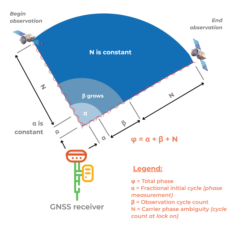
Understanding Carrier Phase Ambiguity
Measuring the phase of a carrier wave allows for much higher accuracy than code-based positioning. However, it comes with a particular challenge: the receiver can measure the received phase, but does not know the exact number of whole cycles traveled between the satellite and itself. This is known as carrier phase ambiguity.
To convert the measurement into an absolute distance, the ambiguity must be “resolved,” meaning the correct number of full cycles must be estimated. This step is critical in positioning techniques like RTK (Real-Time Kinematic) or PPP (Precise Point Positioning), where the accuracy directly depends on the quality of ambiguity resolution.
An incorrect ambiguity “fix” results in a systematic error that can reach several centimeters or more. That’s why high-end receivers include advanced algorithms capable of detecting, modeling, and correcting these uncertainties.
Ambiguity resolution is extensively documented in the literature, notably in the Springer Handbook of GNSS (Teunissen & Montenbruck, 2017), a key reference on the topic.
Main Sources of GNSS Errors
Several factors affect positioning accuracy. Errors may arise from:
From the satellites:
Clock errors: although satellites are equipped with atomic clocks, even tiny drifts can cause positioning errors of several meters.
Orbital errors: discrepancies exist between the satellite’s theoretical position and its actual position.
From the atmosphere:
Ionospheric delay: caused by charged particles in the upper atmosphere; it varies with solar activity.
Tropospheric delay: caused by humidity and pressure in the lower layers of the atmosphere.
From the receiver:
Internal clock drift
Local environment errors: such as multipath effects, obstructions, and interference.
Cycle slips: an intermittent but critical source of error
A cycle slip is a sudden disruption in the tracking of a carrier phase signal by a GNSS receiver. This typically occurs when a temporary obstacle (such as a vehicle, building, or vegetation) blocks or disturbs the signal, even momentarily.
When the signal is reacquired, the receiver resumes phase tracking, but the previous ambiguity is no longer valid—it must be re-estimated. If this detection is poorly handled, it can result in an invisible but long-lasting error.
High-performance receivers, such as Proteus, are equipped with automatic cycle slip detection mechanisms and can restart ambiguity resolution algorithms accordingly. Effective handling of cycle slips is critical in complex environments such as urban areas, forests, or cluttered construction sites.
Signal processing accuracy: depends on the quality of the hardware and the algorithms used.
Type of error | Origin | Order of magnitude |
|---|---|---|
| Satellite clock drift | Space segment | Up to 3 meters |
| Orbital error | Space segment | ±2.5 meters |
| Ionospheric delay | Atmosphere (50–1000 km) | 5 to 50 meters |
| Tropospheric delay | Atmosphere (0–12 km) | 2 to 10 meters |
| Multipath | Receiver / Environment | Variable (meters) |
| Internal measurement noise | Receiver | Centimeter to decimeter level |
Improving Accuracy: GNSS Corrections
To achieve centimeter-level accuracy, GNSS positioning must be corrected. Several techniques exist depending on the use case and operating conditions:
RTK (Real-Time Kinematic) and NRTK (Network RTK): use one or more fixed reference stations to provide real-time correction data. The differential correction data are usually transmitted in the RTCM 10403.3 format, a widely adopted standard in professional GNSS systems.
Base/Rover: involves a mobile base station that sends corrections to a rover in real time. This method requires solid surveying knowledge for proper setup.
PPP (Precise Point Positioning): uses mathematical models to correct various error sources. It takes longer to converge to an accurate solution compared to RTK. PPP relies on highly accurate orbital and clock models, often provided by services such as the IGS (International GNSS Service).
Post-processing: consists of recording raw GNSS observations and processing them afterward. This method is not compatible with real-time applications.
Correction techniques can be applied locally or delivered remotely. This is where the NTRIP protocol (Networked Transport of RTCM via Internet Protocol) comes in, allowing corrections—such as those used in RTK—to be transmitted over the Internet from a correction server to a GNSS receiver.
Syslor’s Proteus GNSS receiver is compatible with real-time correction networks. It also integrates filtering algorithms to compensate for signal propagation effects and temporary signal loss.
Use within the Syslor Ecosystem
To ensure optimal performance for its users in the field, Syslor has made its Proteus GNSS receiver compatible with NRTK corrections. The combination of this technology and the receiver enables the acquisition of precise field data and seamless, real-time mapping integration.
Optimizing GNSS Accuracy in the Field
Even with high-performance equipment and real-time corrections, several factors can still affect positioning quality. Here are some best practices to implement to maximize GNSS measurement reliability:
Monitor ionospheric activity: space weather conditions (magnetic storms, intense solar activity) can temporarily degrade GNSS signals. It is recommended to avoid periods of high ionospheric activity for precision surveys.
Use a reliable correction source: the quality of RTK (or NRTK) corrections is a key factor. Ensure a stable network coverage, a subscription to a reputable service, and a properly configured transmission protocol (such as NTRIP).
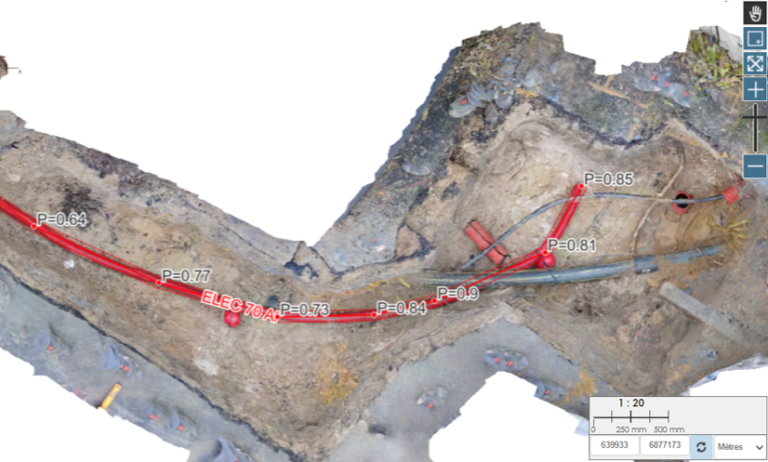
Perform regular field checks: it is advisable to conduct an initial observation at the start of the site, then a second one at the end of the survey to validate measurement stability. This double check helps detect any drifts or occasional errors.
These best practices, combined with the capabilities of the Proteus receiver, help secure the accuracy of collected data, even in challenging environments.
Avoiding Common Errors in GNSS Surveying
Even the most advanced equipment can’t compensate for user errors. Here’s a reminder of common field mistakes and how to avoid them:
Multipath effect (signal reflection)
GNSS signals can bounce off surfaces (vehicles, buildings, water, ground), distorting measurements.
Best practices:
Avoid nearby metallic structures
Use an antenna with an integrated ground plane
Elevate the receiver as much as possible
Bubble level misalignment
A non-vertical pole affects accuracy.
What to do:
Regularly check the level against a vertical structure
Take two observations by rotating the pole 180° to compensate
Use a receiver with built-in tilt compensation if available
Too long baseline
The greater the distance between the base and rover, the more atmospheric errors differ.
Recommendation: use a local base station to reduce baseline length whenever possible.
Coordinate system issues
Without correct localization, your measurements might not align with existing datasets.
Solution: perform local calibration using at least 4 known points.
Unit inconsistency
Using the wrong unit (feet/meters) can distort the entire survey.
Always verify the unit linked to the chosen EPSG system.
Incorrect antenna height input
A wrong reference for receiver height introduces a systematic error.
Check which reference is required (base point, bottom of receiver, phase center, etc.).
Confusion between geoid and ellipsoid
GNSS measures height relative to the ellipsoid, but usable altitudes are orthometric.
Select an appropriate geoid model (e.g., RAF20 in France) to correct this difference.
Conclusion
GNSS positioning is based on complex principles and is subject to numerous sources of error. Understanding these mechanisms allows for better utilization of the capabilities offered by satellite positioning. It is by integrating these considerations that Syslor designed its Proteus GNSS receiver to be reliable, robust, and well-suited to the demands of fieldwork.
To go further
This content is based on principles defined in GNSS specifications and works published by leading organizations in the field. For further study, here are some useful references:
IS-GPS-200 – Specification for the GPS Interface, U.S. Department of Defense – GPS.gov
RTCM 10403.3 – Standard for Differential GNSS Services – RTCM.org
IGS (International GNSS Service) – igs.org
Teunissen, P. J. G., & Montenbruck, O. (2017) – Springer Handbook of Global Navigation Satellite Systems